

Introduction
Today, electronic devices such as smartphones, computers, cars, and smart equipment contain many tiny components. Among them, the Multilayer Ceramic Capacitor (MLCC) is one of the most common electronic components.
Although MLCCs are very small, they play an important role in electronic circuits. They help stabilize voltage, reduce electrical noise, and ensure that electronic devices work properly.
However, because MLCCs are usually hidden inside devices, many people do not know what they are or how they work.
This article will introduce what MLCC is, its advantages, manufacturing process, working principle, different types, and how to choose the right MLCC.
What Is MLCC?
MLCC stands for Multilayer Ceramic Capacitor. It is a type of capacitor that uses ceramic materials as the dielectric layer and multiple layers of electrodes to store electrical energy.
In simple words, an MLCC works like a small energy storage device in an electronic circuit. It can store electrical charge and release it when needed. It also helps keep voltage stable and reduce unwanted electrical noise.
MLCCs are widely used in smartphones, computers, automotive electronics, industrial equipment, communication devices, and many other electronic products.
MLCCs come in different specifications. Their capacitance usually ranges from several picofarads (pF) to dozens of microfarads (μF). Their rated voltage can range from several volts to hundreds of volts depending on the product type.
Common MLCC package sizes include 0201, 0402, 0603, 0805, 1206, and 1210. Smaller packages save space, while larger packages can provide higher capacitance.
Main Performance Advantages of MLCC
MLCCs have become one of the most widely used capacitor types because of their excellent performance.
- High Capacitance in a Compact Size
By stacking multiple ceramic and electrode layers, MLCCs can provide high capacitance while keeping their size very small. - Low Power Loss and Fast Current Response
MLCCs have low Equivalent Series Resistance (ESR), which reduces energy loss and allows them to quickly respond to changes in current. - Excellent Performance in High-Frequency Applications
MLCCs can work effectively in high-frequency circuits, making them widely used in communication devices, RF circuits, and high-speed digital systems. - Long-Term Stability and Reliability
Using stable ceramic materials, MLCCs can provide reliable performance over long periods in consumer electronics, automotive systems, and industrial equipment.
MLCC Manufacturers and Brands
The global MLCC market is mainly dominated by companies from Japan and South Korea. Different manufacturers produce MLCCs for different applications.
- Murata Manufacturing-Japan
Murata is one of the world's largest MLCC manufacturers, offering high-performance MLCCs widely used in smartphones, automotive electronics, communication equipment, and high-reliability applications. - TDK Corporation-Japan
TDK produces a wide range of MLCC products featuring high reliability and stability, mainly used in automotive electronics, industrial equipment, power systems, and electronic devices. - Taiyo Yuden-Japan
Taiyo Yuden provides high-quality MLCCs with excellent electrical characteristics, commonly applied in communication devices, smartphones, and various electronic products. - Samsung Electro-Mechanics-South Korea
Samsung Electro-Mechanics manufactures advanced MLCC products with high capacitance density, widely used in smartphones, computers, automotive electronics, and consumer electronics. - Yageo Corporation-Taiwan, China
Yageo is a major global passive component supplier, producing various MLCCs used in consumer electronics, industrial equipment, automotive systems, and power management applications.
MLCC Structure and Manufacturing Process
MLCC structure
The internal structure of an MLCC is similar to an electronic “sandwich”. It is made by stacking multiple ceramic dielectric layers and metal electrode layers together.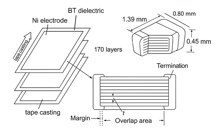
The main parts of an MLCC include:
Ceramic Dielectric Layer : The core material of an MLCC. It stores electrical energy and affects important characteristics such as capacitance and temperature stability.
Internal Electrode Layer : Made of metal materials such as nickel, it creates the electric field inside the capacitor and allows the MLCC to store electrical energy.
External Electrode : Connecting the internal electrodes with the circuit board, it allows the MLCC to be installed and work in an electronic circuit.
Protective Layer: It protects the internal structure and improves reliability.
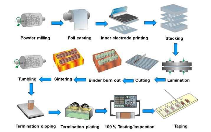
MLCC Manufacturing Process
The production of MLCCs requires high manufacturing accuracy. Through these processes, manufacturers can produce MLCCs with different sizes, capacitance values, and voltage ratings.
The Working Principle of MLCC
An MLCC works based on the basic principle of a capacitor. When voltage is applied between two electrodes, an electric field is created inside the ceramic dielectric material. The capacitor can then store electrical charge.
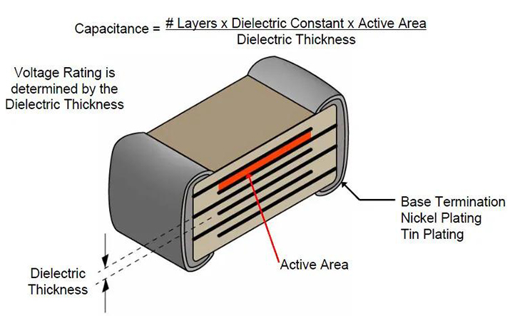
The capacitance value of an MLCC mainly depends on three factors:
The Surface Area of the Electrodes: A larger electrode area allows more charge to be stored, increasing capacitance.
The Distance Between the Electrodes: A smaller distance between electrodes usually increases capacitance.
The Permittivity of the Ceramic Dielectric Material: The dielectric constant of the ceramic material affects how much electrical energy the capacitor can store.
Therefore, manufacturers improve MLCC performance by increasing the number of internal layers, improving ceramic materials, and optimizing the structure.
MLCC Dielectric Material Classification
MLCCs are classified according to the type of ceramic dielectric material used inside them. Different dielectric materials affect the capacitance, stability, temperature characteristics, and application areas of MLCCs.
According to the EIA (Electronic Industries Alliance), MLCC dielectric materials are mainly divided into Class I (Temperature Compensating) and Class II (High Capacitance).
Class I MLCC
Class I MLCCs are designed for applications that require high stability. They usually use ceramic materials such as calcium titanate or magnesium titanate, with small amounts of additives to improve their performance.
Compared with Class II MLCCs, Class I products have better stability, but their capacitance values are usually lower.
Main Features:
- High stability: The capacitance changes very little with temperature, voltage, and time.
- Low loss: They have very low energy loss during operation.
- Good high-frequency performance: They can maintain stable performance in high-frequency circuits.
- High accuracy: They are suitable for circuits that require precise electrical characteristics.
Common Type: NP0/C0G, N750, N1500
Common Applications: Precision analog circuits, RF circuit, Timing circuits, Oscillator circuits, Measurement equipment
Class II MLCC
Class II MLCCs are designed to provide higher capacitance in a smaller size. They mainly use barium titanate (BaTiO₃) ceramic materials with different additives to improve their electrical characteristics.
Compared with Class I MLCCs, Class II products have higher capacitance density and are widely used in modern electronic devices.
Main Features:
- High capacitance density: They can provide larger capacitance values in smaller packages.
- Small size and low cost: They are suitable for mass-produced electronic products.
- Lower stability: Their capacitance is more affected by temperature, voltage, and time.
- DC bias effect: The actual capacitance may decrease when DC voltage is applied.
Common Types: X7R,X5R,Y5V
Common Applications: Smartphone power circuits, Laptop computers, LED driver circuits, DC-DC converters, Power filtering circuits
Comparison of C0G/NP0, X7R, X5R, and Y5V
|
Comparison Item |
C0G / NP0 |
X7R |
X5R |
Y5V |
|
Dielectric Class |
Class I (Temperature Compensating) |
Class II (High Dielectric Constant) |
Class II (High Dielectric Constant) |
Class II (High Dielectric Constant) |
|
Material Characteristics |
Low dielectric constant ceramic with excellent stability |
Barium titanate-based ceramic with balanced performance |
High-K ceramic optimized for high capacitance density |
Ultra-high-K ceramic designed for maximum capacitance |
|
Operating Temperature Range |
-55°C to +125°C |
-55°C to +125°C |
-55°C to +85°C |
-30°C to +85°C |
|
Temperature Coefficient / Capacitance Change |
Within ±30 ppm/°C |
Within ±15% |
Within ±15% |
+22% / -82% |
|
Capacitance Stability |
★★★★★ Excellent |
★★★★☆ Very Good |
★★★☆☆ Moderate |
★☆☆☆☆ Poor |
|
DC Bias Characteristics |
Almost no capacitance loss under DC voltage |
Moderate capacitance reduction under DC bias |
Noticeable capacitance reduction |
Significant capacitance reduction |
|
Aging Characteristics |
Nearly zero aging effect |
Slight capacitance decrease over time |
Moderate aging effect |
Significant aging effect |
|
Dissipation Factor (DF) |
Extremely low |
Low |
Medium |
Higher |
|
High-Frequency Performance |
Excellent |
Good |
Average |
Poor |
|
Maximum Capacitance Range |
Low (pF to nF range) |
Medium to high (nF to μF range) |
High (μF range available) |
Highest capacitance density |
|
Reliability Level |
★★★★★ Highest |
★★★★☆ High |
★★★☆☆ Medium |
★★☆☆☆ Lower |
|
Cost Level |
Higher cost |
Medium |
Medium to low |
Lowest |
|
Typical Applications |
RF circuits, precision circuits, oscillators, filters, timing circuits |
Power supply decoupling, bypass circuits, industrial electronics |
Consumer electronics, compact power circuits, mobile devices |
Low-cost filtering, non-critical applications |
Note: Different manufacturers may have different product specifications. The actual values should be checked in the product datasheet.
Electrical Characteristics of MLCC
The electrical characteristics shown in an MLCC datasheet are measured under specific conditions, usually at room temperature and with little or no DC bias.
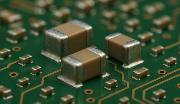
In real circuits, MLCC performance can change because of voltage, temperature, frequency, package size, and dielectric material. Understanding these characteristics helps engineers choose suitable MLCCs and avoid unexpected problems.
Capacitance Value and Tolerance
The capacitance value shown in a datasheet is measured under standard testing conditions. The actual capacitance in a circuit may be different.
Common tolerance ranges include:
C0G/NP0: ±1%, ±2%, or ±5%
X7R/X5R: ±10% or ±20%
For filtering and decoupling circuits, larger tolerance is usually acceptable. For timing circuits, RF circuits, and precision analog circuits, higher accuracy and better stability are required.
Voltage Rating and Derating
MLCCs are available with different voltage ratings, such as 6.3V, 10V, 16V, 25V, 50V, and higher.
In circuit design, engineers usually choose an MLCC with a higher voltage rating than the actual operating voltage to reduce electrical stress, improve reliability, and minimize capacitance loss caused by DC bias effects. For example, in a 5V circuit, a 10V, 16V, or 25V MLCC may be selected instead of a 6.3V MLCC.
This is especially important for Class II MLCCs, such as X5R and X7R, because their capacitance can decrease when a DC voltage is applied.
Temperature Characteristics
The temperature performance of an MLCC depends on its dielectric material.
C0G/NP0 MLCCs provide very stable performance across a wide temperature range. X7R and X5R MLCCs allow greater capacitance changes but provide much higher capacitance density.
For consumer electronics, X5R is often sufficient. For automotive, industrial, or high-temperature applications, X7R, X8R, or automotive-grade MLCCs may be more suitable.
ESR and ESL
MLCCs have two important electrical characteristics: ESR (Equivalent Series Resistance) and ESL (Equivalent Series Inductance)
Compared with many other capacitor types, MLCCs usually have very low ESR and ESL. It can reduce power loss, improve efficiency and allow faster current response. Low ESL helps MLCCs respond quickly to high-frequency noise. This is why MLCCs are widely used near IC power pins, switching regulators, and high-speed digital circuits.
However, extremely low ESR may sometimes cause stability problems in some power circuits. Engineers may solve this by adding damping components or using MLCCs together with other capacitor types.
Frequency Response and Self-Resonance
Every MLCC has a self-resonant frequency. Below this frequency, the MLCC behaves mainly as a capacitor. Above this frequency, the internal parasitic inductance becomes stronger, and the MLCC behaves more like an inductor.
Generally, smaller packages have lower ESL and higher self-resonant frequencies. Larger packages provide higher capacitance but may have weaker high-frequency performance.
Therefore, engineers often use different capacitance values and package sizes together. For example: A 100 nF MLCC can be placed close to an IC pin to remove high-frequency noise. A 10 μF or 22 μF MLCC can be used nearby for voltage stabilization.
Leakage Current and Dielectric Absorption
MLCCs usually have very low leakage current, making them suitable for battery-powered and low-power devices. Their dielectric absorption is also low, especially for C0G/NP0 products. For precision analog circuits, C0G/NP0 is usually a better choice than X7R or X5R.
MLCC Package Sizes
The package size describes the physical dimensions of an MLCC. The industry commonly uses EIA codes, such as 0402, 0603, 0805, and 1206. The first two numbers represent the length, and the last two numbers represent the width.
|
MLCC Package Size |
Dimensions (L × W) |
Capacitance Capability |
Mounting Difficulty |
Relative Cost |
Typical Applications |
|
0201 (0603 Metric) |
0.6 × 0.3 mm |
Lowest capacitance capability |
★★★★★ Very Difficult ;requires high-precision SMT equipment and strict PCB design |
★★★★★ Highest |
Smartphones, wearable devices, RF modules, miniaturized electronic products |
|
0402 (1005 Metric) |
1.0 × 0.5 mm |
Low to medium capacitance capability |
★★★★ Difficult; requires accurate placement and inspection |
★★★★ Higher |
Mobile devices, IoT products, Bluetooth modules, IC decoupling |
|
0603 (1608 Metric) |
1.6 × 0.8 mm |
Medium capacitance capability |
★★★ Moderate; widely supported by standard SMT processes |
★★★ Medium |
Consumer electronics, automotive electronics, general-purpose circuits |
|
0805 (2012 Metric) |
2.0 × 1.25 mm |
Medium to high capacitance capability |
★★ Easy; good handling and soldering reliability |
★★ Lower |
Power filtering, industrial equipment, power supply circuits |
|
1206 (3216 Metric) |
3.2 × 1.6 mm |
High capacitance capability; |
★ Easy; simple assembly and inspection |
★★ Lower |
Automotive electronics, DC/DC converters, industrial control systems |
|
1210 (3225 Metric) |
3.2 × 2.5 mm |
Very high capacitance capability; |
★ Easy; excellent mechanical handling |
★ Low |
Power management systems, high-current circuits, energy storage applications |
|
1812 (4532 Metric) |
4.5 × 3.2 mm |
Higher capacitance capability |
★ Easy; suitable for standard assembly processes |
★ Low |
High-voltage circuits, industrial equipment, power electronics |
|
2220 (5750 Metric) |
5.7 × 5.0 mm |
Highest capacitance capability |
★ Easy; strong mechanical stability |
★ Low |
High-voltage systems, industrial power equipment, automotive applications |
Selecting the Right MLCC
1. Understand the Application Requirements
First, identify the purpose of the capacitor, such as filtering, decoupling, resonant circuits, or high-voltage applications, as different uses require different MLCC characteristics.
2. Choose the Suitable Dielectric Type
Select Class 1 MLCCs (C0G/NP0) when high stability and low loss are required, or choose Class 2 MLCCs (X7R, X5R, Y5V) when higher capacitance is needed.
3. Select the Package Size and Capacitance
Choose a suitable package size, such as 0201, 0402, 0603, or 0805, while balancing capacitance requirements, available space, and reliability.
4. Check Voltage Rating and Reliability
Make sure the rated voltage of the MLCC is higher than the circuit's operating voltage, and choose high-reliability products for demanding applications such as automotive and industrial equipment.
5. Review Manufacturer Specifications
Always check product datasheets for important information, including capacitance tolerance, ESR, ESL, and aging characteristics, and select reliable manufacturers with good quality control.
Conclusion
Although MLCCs are extremely small, they are essential components in modern electronic devices. From smartphones and computers to electric vehicles and industrial systems, MLCCs help stabilize circuits, reduce electrical noise, and improve overall product reliability.
Understanding MLCC structures, materials, electrical characteristics, and selection methods helps engineers and customers choose suitable components for different applications.
Behind many advanced electronic products lie countless tiny MLCCs, quietly supporting the reliable operation of the technologies used in our daily lives.
Frequently Asked Questions
What Is the Full Name of MLCC?
MLCC stands for Multilayer Ceramic Capacitor. It is a ceramic capacitor made by stacking multiple layers of ceramic dielectric materials and internal electrodes, which allows it to provide high capacitance in a compact size.
Which Companies Manufacture MLCCs?
The global MLCC market is mainly supplied by manufacturers including Murata, TDK, Taiyo Yuden, Samsung Electro-Mechanics and Yageo. These companies provide MLCC products for applications such as consumer electronics, automotive electronics, communication equipment, and industrial systems.
What Are the Differences Between Class I and Class II Ceramic Dielectrics?
Class I ceramic dielectrics, such as C0G/NP0, provide excellent stability and low loss but usually have lower capacitance values. Class II dielectrics, such as X7R and X5R, offer higher capacitance density but are more affected by temperature, voltage, and aging.
How Does C0G Compare with X7R MLCCs?
C0G MLCCs provide extremely stable capacitance with very low temperature and voltage effects, making them suitable for precision circuits. X7R MLCCs offer much higher capacitance values in smaller sizes but have greater capacitance variation under different operating conditions.
What Are the Differences Between Tantalum Capacitors and MLCCs?
MLCCs generally provide lower ESR, better high-frequency performance, and smaller sizes, making them suitable for high-speed electronic circuits. Tantalum capacitors offer stable capacitance and high volumetric efficiency, but they typically have different voltage, reliability, and application characteristics.
What Is the Working Principle of an MLCC?
An MLCC stores electrical energy through an electric field created between internal electrodes separated by ceramic dielectric layers. Its capacitance depends on factors such as electrode area, dielectric material properties, and the number of stacked layers.
Why Does an MLCC Show Lower Measured Capacitance than Its Rated Value?
The actual capacitance of an MLCC can be lower than its marked value due to factors such as DC bias effects, measurement conditions, temperature, and frequency. This is especially common in Class II MLCCs like X5R and X7R, where applied voltage can significantly reduce effective capacitance.


