

Introduction
The battery symbol is one of the most fundamental symbols used in circuit diagrams to represent a power source.
This article explains what a battery symbol is, how it works, its common types, and its functions, providing the foundation for understanding battery symbols and reading circuit diagrams accurately.
The Battery in a Circuit
A battery is a power source that converts chemical energy into electrical energy. It supplies the voltage and current required for electronic circuits and devices to operate. From remote controls and smartphones to automotive electronics, batteries play an essential role in providing reliable electrical power.
When a battery is connected to a circuit, chemical reactions occur inside the battery, causing electrons to flow. Electrons travel from the negative terminal through the external circuit and return to the positive terminal, forming a complete electrical circuit.
The battery's output voltage is determined by its electrochemical system, while its operating time mainly depends on its capacity.

Functions of a Battery
A battery does more than simply supply power. It directly affects the stability, operating time, and overall performance of an electronic device. Its primary functions include:
- Supplying Electrical Power: Provides a stable DC power source for electronic circuits and devices.
- Driving Electronic Components: Delivers the energy required for processors, sensors, motors, and other electronic components to operate.
- Powering Portable Devices: Enables portable electronics to function without relying on an external power supply.
- Providing Backup Power: Supplies emergency power to systems such as UPS units, alarm systems, and data storage equipment during power outages.
- Storing Energy: Stores chemical energy and releases it as electrical energy when needed, improving energy availability and utilization.
Types of Batteries
Batteries can be classified according to their electrochemical composition, rechargeability, and intended applications. Common types include carbon-zinc batteries, alkaline batteries, lithium-ion batteries, and lead-acid batteries.
Comparison of Common Battery Types
|
Battery Type |
Nominal Voltage (Per Cell) |
Typical Capacity |
Rechargeable |
Common Applications |
|
Carbon-Zinc Battery |
1.5 V |
Low |
No |
Remote controls, clocks, flashlights |
|
Alkaline Battery |
1.5 V |
Medium to High |
No |
Toys, wireless mice, camera flash units |
|
Lithium-Ion Battery |
3.6–3.7 V |
High |
Yes |
Smartphones, laptops, drones, electric vehicles |
|
Lead-Acid Battery |
2.0 V (per cell) |
High |
Yes |
Automotive starting batteries, electric vehicles, UPS systems, energy storage |
Battery Symbol in Circuit Diagrams
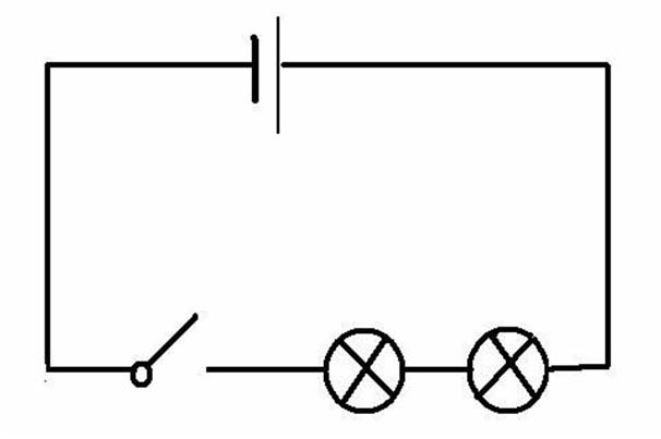
A battery symbol is the standard graphical representation of a power source in a circuit diagram. It clearly indicates the location of the battery and its polarity. By using standardized battery symbols, engineers and technicians can quickly understand how a circuit is powered while reducing the risk of misinterpretation during circuit design, analysis, and maintenance.
International Standards for Battery Symbols
To ensure that circuit diagrams can be understood worldwide, several international organizations have established standards for electrical and electronic symbols. These standards improve drawing consistency while supporting global product design, manufacturing, and technical communication.
International Electrotechnical Commission (IEC)
The IEC develops internationally recognized standards for electrical and electronic technologies. IEC 60617, Graphical Symbols for Diagrams, defines the standard graphical symbols used in circuit diagrams, including those for batteries, resistors, capacitors, and many other electrical components. It serves as one of the primary references for electrical schematic design worldwide.
Institute of Electrical and Electronics Engineers (IEEE)
IEEE develops technical standards covering electrical engineering, electronics, telecommunications, and related technologies. Its standards and engineering guidelines are widely adopted in circuit design, electronic system development, and engineering practice, providing a consistent technical framework for the electronics industry.
International Organization for Standardization (ISO)
ISO develops international standards across a wide range of industries, including manufacturing, quality management, and information technology. Although ISO does not specifically define circuit diagram symbols, many of its standards complement IEC standards, helping promote consistency and interoperability in electronic products worldwide.
Functions of Battery Symbols in Circuit Diagrams
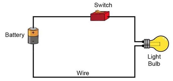
A battery symbol does more than simply identify a power source. It conveys essential information that helps engineers understand how a circuit is powered and how it operates.
Indicates the Power Source Location
The battery symbol clearly identifies where the power supply is located within the circuit, making it the starting point for analyzing the circuit's power distribution.
Identifies Power Polarity
The longer and shorter lines indicate the positive and negative terminals, allowing engineers to connect components with the correct polarity and reduce wiring errors.
Shows the Power Configuration
By identifying whether the circuit uses a single cell or multiple cells connected in series, the battery symbol helps engineers determine the circuit's supply voltage configuration.
Improves Drawing Consistency
Standardized battery symbols ensure that circuit diagrams produced by different engineers follow the same graphical conventions, making them easier to review, maintain, and share.
Supports Troubleshooting
During equipment maintenance, technicians can quickly locate the power supply section by identifying the battery symbol, making it easier to diagnose power-related faults.
Applications of Battery Symbols in Circuit Diagrams
Battery symbols are used in virtually every circuit diagram that includes a DC power source. They are an essential part of electrical and electronic documentation across many industries.
Consumer Electronics
Circuit diagrams for smartphones, tablets, wireless earbuds, remote controls, and other portable devices use battery symbols to represent their power supply.
Automotive Electronics
Standard battery symbols are widely used in schematics for automotive batteries, start-stop systems, electric vehicle battery packs, and Electronic Control Units (ECUs).
Industrial Control Systems
Battery symbols identify DC power modules and backup power sources in Programmable Logic Controllers (PLCs), sensors, measuring instruments, and industrial automation equipment.
Renewable Energy and Energy Storage Systems
Electrical diagrams for photovoltaic (PV) energy storage systems, Battery Management Systems (BMS), residential energy storage, and utility-scale battery installations all use standardized battery symbols to represent different battery configurations.
Engineering Education and Research
Battery symbols are widely used in textbooks, laboratory manuals, technical papers, and research publications to help students, educators, and engineers accurately understand circuit structures and power distribution.
How to Identify the Positive and Negative Terminals
Correctly identifying the positive and negative terminals of a battery is one of the first steps in reading a circuit diagram. Misinterpreting the polarity can lead to incorrect circuit analysis, improper component installation, or even equipment failure. Therefore, engineers and technicians should always verify battery polarity before designing, assembling, or troubleshooting a circuit.
Positive Terminal (+)
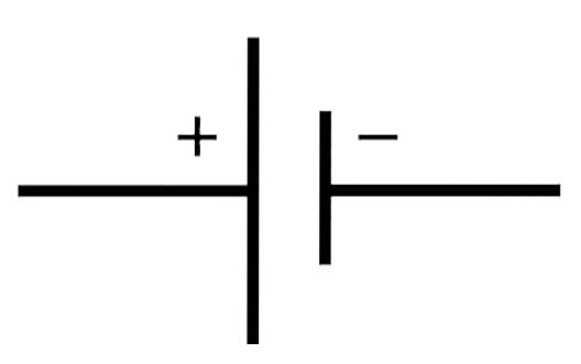
In the standard battery symbol, the longer parallel line represents the positive terminal (+). The positive terminal has the higher electric potential.
Under the conventional current model, current flows from the positive terminal, passes through the load, and returns to the negative terminal.
In most circuit diagrams, the positive terminal is also labeled with a "+" sign for easier identification.
Negative Terminal (−)
The shorter parallel line represents the negative terminal (−). The negative terminal has the lower electric potential and serves as the source of electron flow.
Note: Circuit analysis generally follows the conventional current direction, which assumes current flows from the positive terminal to the negative terminal. In contrast, electron flow is considered to move from the negative terminal to the positive terminal.
Why Is Battery Polarity Important?
Battery polarity determines the direction of current flow and is essential for the proper operation of electronic circuits. Whether the circuit is a simple LED application or a complex electronic system, the power supply must always be connected with the correct polarity.
Incorrect polarity may result in the following problems:
- electronic components fail to operate properly
- damage to electronic components
- circuit malfunctions
- increased safety risks
Different Types of Battery Symbols
Battery symbols vary depending on the number of cells, power configuration, and application. Although they all represent power sources, each symbol conveys different information about the battery and its intended use.
Single Cell Battery
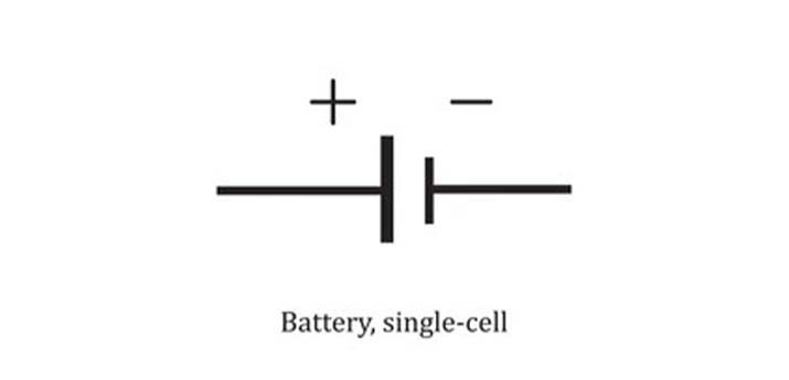
A single-cell battery is represented by one pair of parallel lines, with the longer line indicating the positive terminal and the shorter line indicating the negative terminal. This is the most commonly used battery symbol and typically represents a single dry cell, button cell, or lithium battery.
Double Cell Battery
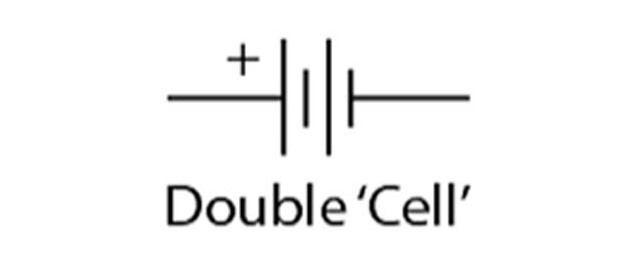
A double-cell battery is represented by two pairs of long and short parallel lines arranged in sequence. It indicates that two battery cells are connected in series, producing a higher output voltage than a single cell. This symbol is commonly found in portable electronic devices that require a higher supply voltage.
Multi Cell Battery
A multi-cell battery is represented by multiple battery cells connected in series. When the battery contains many cells, the symbol is typically drawn with an ellipsis (...) between the first and last battery cells to indicate that additional cells are omitted from the drawing. This representation keeps the schematic clear while showing that the battery pack consists of more than two cells connected in series.
It is commonly used in battery packs for laptops, power tools, energy storage systems, electric vehicles, and other applications that require higher operating voltages.

Adjustable Voltage Battery
An adjustable voltage power source is typically represented by a standard DC power symbol combined with an adjustment indicator, such as an arrow. It indicates that the output voltage can be varied within a specified range and is commonly used for laboratory DC power supplies and adjustable bench power supplies.

Lead-Acid Battery Pack
A lead-acid battery pack typically consists of multiple 2 V lead-acid cells connected in series. In circuit diagrams, it is usually represented by a multi-cell battery symbol together with its rated voltage, such as 12 V or 24 V, or a battery pack designation. This symbol is widely used in automotive systems, forklifts, UPS systems, and backup power applications.
Damaged or Faulty Battery
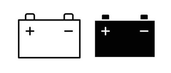
A damaged or faulty battery is typically represented by a battery symbol combined with a warning mark, such as a cross (×) or an exclamation mark (!). It indicates abnormal battery conditions, including capacity degradation, overheating, physical damage, or charging failure. This symbol is commonly used in Battery Management Systems (BMS), diagnostic software, and maintenance documentation.

Steps to Identify a Battery in a Circuit Diagram
Whether you are learning electronics, reading circuit schematics, or troubleshooting electronic equipment, knowing how to identify a battery symbol is an essential skill. Following a systematic approach not only helps you locate the power source quickly but also reduces the risk of misinterpreting the circuit.
1. Locate the Battery Symbol
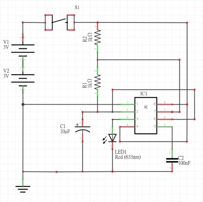
Begin by finding the battery symbol, which is typically represented by one or more pairs of long and short parallel lines, or by a DC power source symbol. The battery is usually positioned at the input side of the circuit and serves as the starting point for analyzing the circuit's power distribution.
2. Identify the Positive and Negative Terminals
Determine the battery polarity according to the standard battery symbol. The longer line represents the positive terminal (+), while the shorter line represents the negative terminal (−). If polarity markings or voltage values are provided, use them to confirm the correct power orientation.
3. Determine the Number of Cells and Their Configuration
Count the number of long and short line pairs to determine whether the symbol represents a single cell or a multi-cell battery pack. Multiple pairs of lines generally indicate cells connected in series to provide a higher output voltage.
4. Check the Voltage or Battery Label
Circuit diagrams often include additional information near the battery symbol, such as the rated voltage, battery type, or model designation—for example, 3 V, 5 V, 12 V, or Li-ion Battery. These markings help identify the power source and verify whether it meets the circuit's electrical requirements.
5. Trace the Power Path
Starting from the battery symbol, follow the connecting wires to determine how electrical power is distributed throughout the circuit. Analyzing the power path together with other circuit symbols provides a clearer understanding of how the entire circuit functions.
Common Mistakes When Interpreting Battery Symbols
Although battery symbols are relatively simple, they are often misunderstood when reading circuit diagrams. Misinterpreting these symbols can lead to incorrect circuit analysis, wiring mistakes, or equipment malfunction. Understanding the most common errors can help improve accuracy when reading electrical schematics.
Reversing the Battery Polarity
One of the most common mistakes is confusing the meanings of the long and short parallel lines. Reversed polarity may prevent components such as LEDs, electrolytic capacitors, and integrated circuits from operating correctly, and in some cases, it may permanently damage the components.
Confusing a Single Cell with a Multi-Cell Battery Pack
Some readers focus only on the battery symbol itself while overlooking the number of line pairs. As a result, a multi-cell battery pack may be mistaken for a single-cell battery, leading to incorrect assumptions about the circuit's operating voltage.

Ignoring the Battery Chemistry
Circuit diagrams may include labels such as Li-ion, Lead-acid, or NiMH to indicate the battery chemistry. Ignoring this information may result in selecting an incompatible replacement battery, which can affect performance, safety, or service life.
Overlooking Voltage and Other Specifications
Battery symbols are often accompanied by important information such as rated voltage, capacity, or battery pack specifications. Ignoring these details may lead to selecting an unsuitable power source that does not meet the circuit's design requirements.
Assuming Every DC Power Symbol Represents a Battery
Not every DC power symbol refers to an actual battery. Some symbols represent regulated DC power supplies, laboratory power supplies, or USB power sources. Always consider the symbol style, accompanying labels, and the circuit's intended application before identifying the power source.
Analyzing the Battery Symbol in Isolation
A battery symbol represents only one part of a circuit. Examining it without considering the surrounding components and wiring may result in an incomplete understanding of the circuit's operation. For accurate analysis, always interpret the battery symbol together with the entire schematic.
Frequently Asked Questions
What Does a Battery Symbol Look Like in a Circuit Diagram?
A battery symbol is typically shown as one long parallel line and one short parallel line, representing the positive and negative terminals, respectively. When multiple cells are connected in series, additional cell symbols or an ellipsis (...) may be used to indicate a battery pack.
How Is a Battery Represented in a Circuit Diagram?
A battery is represented using standardized graphical symbols rather than realistic drawings. The symbol clearly identifies the power source and its polarity, allowing engineers to read and interpret circuit diagrams consistently.
What Are the Terminals of a Battery in a Circuit?
A standard battery symbol identifies two terminals: the positive terminal (+), shown by the longer line, and the negative terminal (-), shown by the shorter line. Correctly identifying these terminals is essential for proper circuit assembly and operation.
What Is the Correct Way to Connect Batteries in Series?
To connect batteries in series, the positive terminal of one battery is connected to the negative terminal of the next battery. This configuration increases the total output voltage while the battery pack capacity (Ah) remains the same as that of a single cell.
How Can You Identify and Fix Battery Symbol Mistakes in a Circuit Diagram
Start by checking the battery polarity, voltage labels, and the number of battery cells shown in the schematic. Comparing the symbol with the IEC standard and verifying the circuit connections can help identify incorrect polarity, missing labels, or symbol interpretation errors.


