

A capacitor is a passive electronic component that stores electrical energy in an electric field. Understanding capacitor symbols helps students, engineers, and technicians quickly identify capacitors and their functions in circuit diagrams.
This guide explains what capacitors are, the main types of capacitors, common capacitor symbols, international standards, capacitance values and units, and how to identify capacitor symbols in circuit diagrams.
What Is a Capacitor?
A capacitor is a passive electronic component that stores electrical energy in an electric field. It is commonly used for filtering, coupling, timing, smoothing, and energy storage in electronic circuits.
A basic capacitor consists of two conductive plates separated by an insulating material called a dielectric. When a voltage is applied, electric charge builds up on the two plates, creating an electric field between them. The dielectric helps separate the plates and affects the capacitance of the component.
Types of Capacitors
Capacitors can be classified according to their dielectric material, construction, electrical characteristics, and intended application.
|
Type |
Description |
Typical Uses |
|
Ceramic Capacitor |
Uses ceramic as the dielectric. It is usually non-polarized and is available in many capacitance values. |
Decoupling, bypassing, filtering, and RF circuits |
|
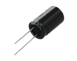
Electrolytic Capacitor |
Uses an electrochemical dielectric layer and provides relatively high capacitance in a compact size. Many common electrolytic capacitors are polarized. |
Power supply filtering, smoothing, and bulk energy storage |
|
Tantalum Capacitor |
A type of electrolytic capacitor that uses tantalum-based construction. It offers good capacitance per volume and stable characteristics in many applications. |
Filtering, bypassing, coupling, and compact electronic devices |
|
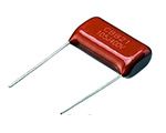
Film Capacitor |
Uses a thin plastic film as the dielectric. Different film materials provide different electrical characteristics. |
Power electronics, audio circuits, filtering, and timing circuits |
|
Mica Capacitor |
Uses mica as the dielectric and is known for good stability and low loss. |
RF circuits and applications requiring stable capacitance |
|
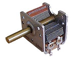
Variable Capacitor |
Allows its capacitance to be adjusted over a range. |
Tuning and matching circuits, especially in RF applications |
|
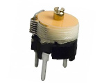
Trimmer Capacitor |
A small adjustable capacitor normally used for calibration or fine adjustment rather than frequent operation. |
Circuit tuning and calibration |
What Is a Capacitor Symbol?
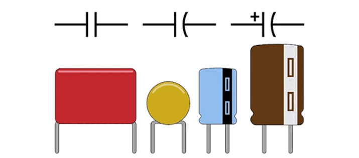
A capacitor symbol is a graphical representation used to show a capacitor in a circuit diagram. Instead of drawing the physical component, a schematic uses a simple symbol to show its electrical function and connection points.
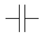
The basic capacitor symbol consists of two conductive lines separated by a small gap. The two lines represent the two electrodes or plates of the capacitor. Additional marks can be added to the basic symbol to indicate features such as polarity or adjustable capacitance.
Why Is It Important to Understand Capacitor Symbols
- Identify components: A capacitor symbol helps readers quickly find capacitors in a circuit diagram.
- Understand polarity: A polarized symbol indicates that the capacitor has a positive and negative terminal.
- Recognize component types: Special marks can show whether a capacitor is variable, adjustable, or designed for a special function.
- Read circuit connections: The symbol shows how the capacitor is connected to other components.
- Understand circuit function: Capacitors are commonly used for filtering, coupling, timing, bypassing, and energy storage.
Standards for Capacitor Symbols
International standards are essential for ensuring that capacitor symbols are understood in the same way across different countries and engineering fields. They provide a unified visual language for circuit diagrams, making design, communication, and manufacturing more consistent and less error-prone.
These standards are developed and maintained by several major international organizations:
International Electrotechnical Commission (IEC)
The IEC is the main global organization responsible for standardizing electrical and electronic technologies.
It develops widely used standards such as IEC 60617, which defines official graphical symbols for circuit diagrams, including capacitors and other passive components. These standards help engineers around the world read and design circuits with consistent and unambiguous symbols.
Institute of Electrical and Electronics Engineers (IEEE)
IEEE is a global professional association that creates technical standards for electrical engineering, electronics, and computing.
In collaboration with ANSI, it defines symbol conventions and reference designations used in circuit diagrams, ensuring clear and consistent documentation, especially in North American engineering practice.
International Organization for Standardization (ISO)
ISO develops international standards across a wide range of industries, including electronics, manufacturing, and information systems.
Although it does not focus specifically on circuit symbols, its broader standardization frameworks support consistency, quality control, and interoperability in global engineering and industrial processes.
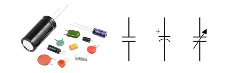
Types of Capacitor Symbols in Circuits
Capacitor symbols can be divided into basic and special symbols. The basic symbols identify non-polarized and polarized capacitors, while special symbols provide additional information about adjustable or specialized capacitor characteristics.
Basic Capacitor Circuit Symbols
Non-Polarized Capacitor Symbol
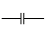
The non-polarized capacitor symbol is normally drawn as two parallel straight lines with a gap between them. It does not indicate a positive or negative terminal, so the capacitor can generally be connected in either direction.
Ceramic and film capacitors are common examples of non-polarized capacitors. They are widely used in filtering, bypassing, coupling, and timing circuits.

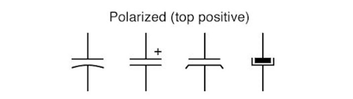
Polarized Capacitor Symbol
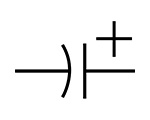
A polarized capacitor symbol includes an additional indication of polarity, such as a positive sign or a modified plate. This tells the reader that the capacitor has defined positive and negative terminals.
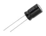
Aluminum electrolytic and tantalum capacitors are common polarized capacitor types. They must be connected with the correct polarity in applications that require polarized operation.
Special Capacitor Symbols
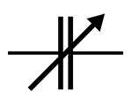
Variable Capacitor Symbol
A variable capacitor symbol is based on the basic capacitor symbol with an additional diagonal arrow. The arrow indicates that the capacitance can be adjusted.
Variable capacitors are mainly used in tuning and matching circuits, especially in RF applications.

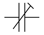
Trimmer Capacitor Symbol
A trimmer capacitor is a small adjustable capacitor designed mainly for calibration or fine adjustment. Its symbol is similar to a variable capacitor symbol but uses a different adjustment indication in many schematic conventions.
Trimmer capacitors are commonly used when a circuit needs a small capacitance adjustment during setup or calibration.

Feed-Through Capacitor Symbol
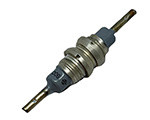
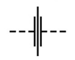
A feed-through capacitor is designed to pass a signal or power connection through a barrier while providing capacitance for filtering unwanted high-frequency noise. Its symbol includes the capacitor function together with a feed-through connection.
Feed-through capacitors are commonly used for electromagnetic interference (EMI) filtering and high-frequency noise suppression.

Bipolar Capacitor Symbol
A bipolar capacitor is designed to operate when the voltage polarity can change. Its symbol does not indicate a fixed positive or negative terminal in the same way as a polarized capacitor.
Bipolar electrolytic capacitors can be used in applications where the voltage across the capacitor may reverse, including some AC and signal applications.

Temperature-Dependent Capacitor (TDR) Symbol
A temperature-dependent capacitor has a capacitance that changes with temperature. Its symbol is based on the capacitor symbol with an additional marking to show its temperature-dependent characteristic.
These capacitors can be used in circuits where capacitance needs to change with temperature or where temperature effects need to be compensated.

Common Capacitor Types and Their Symbols
|
Capacitor Name |
Physical Image |
Circuit Symbol |
|
Ceramic Capacitor |
|
|
|
Film Capacitor |
|
|
|
Aluminum Electrolytic Capacitor |
|
|
|
Tantalum Capacitor |
|
|
|
Variable Capacitor |
|
|
|
Trimmer Capacitor |
|
|
|
Feed-Through Capacitor |
|
|
|
Bipolar Capacitor |
|
|



The Capacitance of a Capacitor
What Is Capacitance?
Capacitance describes a capacitor's ability to store electric charge for a given voltage. It is represented by the letter C and is an important value when selecting or identifying a capacitor.
For a basic parallel-plate capacitor, capacitance can be expressed as:

The formula shows several important factors that affect capacitance:
- Plate area (S): A larger plate area generally produces higher capacitance.
- Plate distance (d): A smaller distance between the plates generally produces higher capacitance.
- Dielectric material (ε): A material with higher permittivity can increase capacitance.
Capacitance Units and Conversion Formulas
Capacitance is measured in farads (F). Because one farad is a large unit for many practical electronic components, smaller SI units such as microfarads, nanofarads, and picofarads are commonly used.
|
Name |
Symbol |
Conversion |
Common Application |
|
Farad |
F |
1 F |
Very large capacitance values and energy-storage applications |
|
Microfarad |
µF |
1 µF = 10⁻⁶ F |
Power supply filtering and larger capacitors |
|
Nanofarad |
nF |
1 nF = 10⁻⁹ F |
Filtering, timing, and general electronic circuits |
|
Picofarad |
pF |
1 pF = 10⁻¹² F |
RF, tuning, oscillators, and high-frequency circuits |
Useful conversions include:
1 F = 1,000,000 µF
1 µF = 1,000 nF
1 nF = 1,000 pF
1 µF = 1,000,000 pF
How to Identify Capacitor Symbols in a Circuit
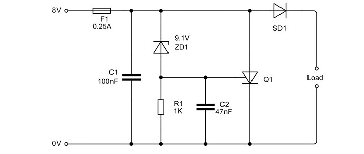
Follow these steps when identifying a capacitor symbol in a circuit diagram:
1. Look for the basic capacitor shape
Start by looking for two conductive lines separated by a small gap. This is the basic visual form used to represent a capacitor in a schematic.
2. Check whether the capacitor is polarized
Look for a polarity indication such as a plus sign or another marking that identifies the positive terminal. If polarity is shown, the component should not be treated as an ordinary non-polarized capacitor.
3. Check for additional symbol markings
A diagonal arrow or other additional marking can indicate an adjustable or specialized capacitor. These markings help distinguish variable, trimmer, and other special capacitor symbols.
4. Read the reference designator and capacitance value
Capacitors are commonly identified by the letter C followed by a number, such as C1 or C2. The circuit diagram may also show the capacitance value, such as 100 nF or 10 µF. Real circuit documentation uses designators such as C1 to identify capacitors.
5. Check the capacitor's role in the circuit
Look at the components connected around the capacitor. Its position can provide useful information about whether it is being used for filtering, bypassing, coupling, timing, or another circuit function. Capacitors are used for many of these functions in both analog and digital circuits.
6. Confirm the component information when necessary
For a real circuit, do not identify a capacitor from the symbol alone. Check the circuit notes, bill of materials, schematic values, or component datasheet when the exact type or rating is important.
Conclusion
The capacitor symbol is a simple but important part of reading circuit diagrams. The basic symbol represents the capacitor, while additional markings can show polarity, adjustment, or other characteristics.
Learning the main capacitor symbols makes it easier to understand circuit diagrams and identify how capacitors are used. By combining the symbol with the capacitance value, reference designator, and surrounding circuit connections, beginners can read capacitor information more accurately.
Frequently Asked Questions
What Is the Capacitor Symbol?
A capacitor is represented by a standardized graphical symbol in a circuit diagram, typically showing two conductive plates separated by a gap. IEC 60617 includes standardized capacitor symbols for use in electrotechnical diagrams
What Does the μF Symbol Mean in Capacitor Specifications?
The symbol µF stands for microfarad, a unit used to express capacitance. One microfarad equals 10⁻⁶ farads, and capacitance is a measure of how much electric charge a capacitor can store per unit of voltage.
How Do Polarized and Non-polarized Capacitors Differ in Circuits?
Polarized capacitors have defined positive and negative terminals and must be connected with the correct polarity in applications that require polarized operation. Non-polarized capacitors do not have a fixed positive or negative terminal and can generally be connected in either direction.
Why Are Different Capacitor Symbols Used in Schematic Diagrams?
Different capacitor symbols provide information about the component's characteristics, such as polarity, adjustability, or temperature dependence.
What Is the Main Function of a Capacitor?
A capacitor stores electric charge and electrical energy and can release that energy when needed. Capacitors are used in many circuits for functions such as filtering, signal coupling, timing, and energy storage.


